Silicon时钟振荡器数据手册
We are a leader in secure, intelligent wireless technology for a more connected world. Our integrated hardware and software platform, intuitive development tools, unmatched ecosystem and robust support make us the ideal long-term partner in building advanced industrial, commercial, home and life applications. We make it easy for developers to solve complex wireless challenges throughout the product lifecycle and get to market quickly with innovative solutions that transform industries, grow economies and improve lives.
自推出以来32.768kHz微型手表水晶已成为有史以来最受欢迎的计时参考。这申请说明旨在为使用石英晶体在计时应用中的应用。
几乎在所有情况下,设计者都希望使用简单的逻辑为了方便和费用通常适用于此类设计的标准是应该是准确的、低成本的和低功耗的。使用手表晶体和CMOS逻辑所有这些标准都可以满足。
在CMOS振荡器电路中,功耗随频率而增加因此,将操作频率降低到最低限度这就是选择32.768KHz晶振的原因。第二种方式降低CMOS电路功耗的方法是减小尺寸驱动的任何负载。部分原因是手表晶体设计为通常在12.5 pF负载下运行,而不是更常见的是20或30pF。它还与:
(a)CMOS的类型在手表使用的低电压下,所用的蒸汽会耗尽除非使用低晶体负载电容;
(b) 保存水晶低驱动电平,同时保持足够的逆变器输入电压,以及
(c) 以允许使用非常小的微调电容器,同时仍然提供必要的修整范围。
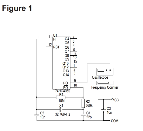
可以满足CMOS反相器时钟振荡器的基本要求具有单个栅极和少数其他组件以提供偏置以及反馈。图1显示了这种类型的典型电路。负载石英晶体的电容是Cout和Cin以及包括逻辑门在内的任何电路偏移输入和输出引脚电容。中使用的组件值图1工作良好,与测量的测试结果具有良好的相关性从Saunders 140晶体阻抗计获得。明显的呈现给晶体的负载电容为:


Cout=栅极输出电容器Cin=栅极输入电容器这给出了6.9pF负载的数字。这远远低于要求12.5pF的数字,但是逻辑的输入和输出引脚闸门有相当大的负荷。这些附加值需要添加到6.9pF。这些负载通常在3pF到每个引脚4pF,但最高可达10pF,也取决于逻辑家庭使用。这些额外的负载加上电路应加起来约为12.5pF。Silicon时钟振荡器数据手册
如果需要可微调振荡器,22pF输出电容器可以由固定的10pF电容器与2pF至22pF并联代替修剪器。为了获得最佳结果,应使用NPO、COG或类似的低温系数电介质电容器以获得最佳稳定性。
对这种晶体振荡器的一个经常表达的要求是接近公差,通常是在没有规定的布局中用于修剪器。除了电容器公差的影响外意识到,由于它们的值较低归因于IC的阻抗将导致某种程度上的不确定相移,因此振荡频率。建议使用修剪器因此,如果需要优于±50ppm的精度,而与实际的晶体容差无关。

另一个重要的影响是由于温度的变化。1MHz以下的手表晶体和其他类似类型具有抛物线设计周转温度为25°C时的频率-温度特性(见图3)。营业额的容差温度和抛物线曲率常数,通常为±3°C和0.038 ppm/°C2,这意味着精密公差可以
仅在有限的温度范围内保持。
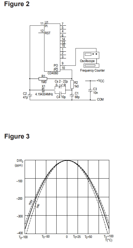
4.194304MHz(32.768kHz x 27)AT切割晶体的类似电路如图2所示,C3和C4旨在促进精确用标准时钟校准晶体的频率微调晶体负载12pF。如果不需要修剪,则更换具有18pF或22pF固定单元的电容器(选择导致最接近标称频率的振荡),或省略它们并指定用于在30pF负载下校准的晶体。
Since its introduction the 32.768kHz miniature watch crystal
has become the most popular time keeping reference ever. This
application note is intended to give some guidance as to the use of
quartz crystals in time keeping applications.Silicon时钟振荡器数据手册
原厂代码
品牌
型号
频率
电压
频率稳定度
530FC311M040DGR
Silicon振荡器
Si530
311.04MHz
2.5V
±7ppm
530FC622M080DGR
Silicon振荡器
Si530
622.08MHz
2.5V
±7ppm
531AC250M000DGR
Silicon振荡器
Si531
250MHz
3.3V
±7ppm
531AC311M040DGR
Silicon振荡器
Si531
311.04MHz
3.3V
±7ppm
531AC622M080DGR
Silicon振荡器
Si531
622.08MHz
3.3V
±7ppm
531BC250M000DGR
Silicon振荡器
Si531
250MHz
3.3V
±7ppm
531BC311M040DGR
Silicon振荡器
Si531
311.04MHz
3.3V
±7ppm
531BC622M080DGR
Silicon振荡器
Si531
622.08MHz
3.3V
±7ppm
531EC250M000DGR
Silicon振荡器
Si531
250MHz
2.5V
±7ppm
531EC311M040DGR
Silicon振荡器
Si531
311.04MHz
2.5V
±7ppm
531EC622M080DGR
Silicon振荡器
Si531
622.08MHz
2.5V
±7ppm
531FC250M000DGR
Silicon振荡器
Si531
250MHz
2.5V
±7ppm
531FC311M040DGR
Silicon振荡器
Si531
311.04MHz
2.5V
±7ppm
531FC622M080DGR
Silicon美国晶振
Si531
622.08MHz
2.5V
±7ppm
530CA40M0000BG
Silicon振荡器
Si530
40MHz
3.3V
±50ppm
531AA640M000BG
Silicon振荡器
Si531
640MHz
3.3V
±50ppm
501BCAM032768BAG
Silicon振荡器
Si501
32.768kHz
3.3V
±20ppm
501BCAM032768DAF
Silicon振荡器
Si501
32.768kHz
3.3V
±20ppm
501JCAM032768BAF
Silicon振荡器
Si501
32.768kHz
3.3V
±20ppm
501JCAM032768BAG
Silicon振荡器
Si501
32.768kHz
3.3V
±20ppm
501JCAM032768CAG
Silicon振荡器
Si501
32.768kHz
3.3V
±20ppm
501HCAM032768BAG
Silicon振荡器
Si501
32.768kHz
1.7 V ~ 3.6 V
±20ppm
501HCAM032768CAF
Silicon振荡器
Si501
32.768kHz
1.7 V ~ 3.6 V
±20ppm
501HCAM032768CAG
Silicon振荡器
Si501
32.768kHz
1.7 V ~ 3.6 V
±20ppm
501HCAM032768DAG
Silicon振荡器
Si501
32.768kHz
1.7 V ~ 3.6 V
±20ppm
501ABA8M00000CAF
Silicon振荡器
Si501
8MHz
1.7 V ~ 3.6 V
±30ppm
501ABA8M00000DAF
Silicon振荡器
Si501
8MHz
1.7 V ~ 3.6 V
±30ppm
501ABA8M00000DAG
Silicon振荡器
Si501
8MHz
1.7 V ~ 3.6 V
±30ppm
501ACA10M0000CAG
Silicon振荡器
Si501
10MHz
1.7 V ~ 3.6 V
±20ppm
501ACA10M0000DAF
Silicon振荡器
Si501
10MHz
1.7 V ~ 3.6 V
±20ppm
501ACA10M0000DAG
Silicon振荡器
Si501
10MHz
1.7 V ~ 3.6 V
±20ppm
501JCA10M0000CAF
Silicon振荡器
Si501
10MHz
3.3V
±20ppm
501JCA10M0000CAG
Silicon振荡器
Si501
10MHz
3.3V
±20ppm
501JCA10M0000DAF
Silicon振荡器
Si501
10MHz
3.3V
±20ppm
501JCA10M0000DAG
Silicon振荡器
Si501
10MHz
3.3V
±20ppm
501HCA12M0000BAG
Silicon振荡器
Si501
12MHz
1.7 V ~ 3.6 V
±20ppm
501HCA12M0000CAF
Silicon振荡器
Si501
12MHz
1.7 V ~ 3.6 V
±20ppm
501HCA12M0000CAG
Silicon振荡器
Si501
12MHz
1.7 V ~ 3.6 V
±20ppm
501HCA12M0000DAG
Silicon振荡器
Si501
12MHz
1.7 V ~ 3.6 V
±20ppm
501BCA16M0000DAF
Silicon振荡器
Si501
16MHz
3.3V
±20ppm
501BCA16M0000DAG
Silicon振荡器
Si501
16MHz
3.3V
±20ppm
501BAA16M0000BAF
Silicon振荡器
Si501
16MHz
3.3V
±50ppm
501BAA16M0000CAF
Silicon振荡器
Si501
16MHz
3.3V
±50ppm
501BAA16M0000DAG
Silicon振荡器
Si501
16MHz
3.3V
±50ppm
501JCA20M0000BAF
Silicon振荡器
Si501
20MHz
3.3V
±20ppm
501JCA20M0000BAG
Silicon振荡器
Si501
20MHz
3.3V
±20ppm
501JCA20M0000CAF
Silicon振荡器
Si501
20MHz
3.3V
±20ppm
501JCA20M0000DAF
Silicon振荡器
Si501
20MHz
3.3V
±20ppm
501JCA20M0000DAG
Silicon振荡器
Si501
20MHz
3.3V
±20ppm
501AAA24M0000CAF
Silicon振荡器
Si501
24MHz
1.7 V ~ 3.6 V
±50ppm
501AAA24M0000CAG
Silicon振荡器
Si501
24MHz
1.7 V ~ 3.6 V
±50ppm
501AAA24M0000DAF
Silicon振荡器
Si501
24MHz
1.7 V ~ 3.6 V
±50ppm
501AAA24M0000DAG
Silicon振荡器
Si501
24MHz
1.7 V ~ 3.6 V
±50ppm
501JAA24M0000BAF
Silicon振荡器
Si501
24MHz
3.3V
±50ppm
501JAA24M0000CAG
Silicon振荡器
Si501
24MHz
3.3V
±50ppm
501JAA24M0000DAG
Silicon振荡器
Si501
24MHz
3.3V
±50ppm
501JCA24M0000BAF
Silicon振荡器
Si501
24MHz
3.3V
±20ppm
501JCA24M0000BAG
Silicon振荡器
Si501
24MHz
3.3V
±20ppm
501JCA24M0000CAG
Silicon振荡器
Si501
24MHz
3.3V
±20ppm
501JCA24M0000DAG
Silicon振荡器
Si501
24MHz
3.3V
±20ppm
501AAA25M0000BAG
Silicon振荡器
Si501
25MHz
1.7 V ~ 3.6 V
±50ppm
501AAA25M0000CAF
Silicon振荡器
Si501
25MHz
1.7 V ~ 3.6 V
±50ppm
501AAA25M0000CAG
Silicon振荡器
Si501
25MHz
1.7 V ~ 3.6 V
±50ppm
501AAA25M0000DAF
Silicon振荡器
Si501
25MHz
1.7 V ~ 3.6 V
±50ppm
501JAA25M0000CAF
Silicon振荡器
Si501
25MHz
3.3V
±50ppm
501JAA25M0000CAG
Silicon振荡器
Si501
25MHz
3.3V
±50ppm
501JAA25M0000DAF
Silicon振荡器
Si501
25MHz
3.3V
±50ppm
501JAA25M0000DAG
Silicon振荡器
Si501
25MHz
3.3V
±50ppm
501JCA25M0000BAF
Silicon振荡器
Si501
25MHz
3.3V
±20ppm
501JCA25M0000BAG
Silicon振荡器
Si501
25MHz
3.3V
±20ppm
501JCA25M0000CAG
Silicon振荡器
Si501
25MHz
3.3V
±20ppm
501JCA25M0000DAF
Silicon振荡器
Si501
25MHz
3.3V
±20ppm
501JCA25M0000DAG
Silicon振荡器
Si501
25MHz
3.3V
±20ppm
501HCA26M0000BAG
Silicon振荡器
Si501
26MHz
1.7 V ~ 3.6 V
±20ppm
501HCA26M0000CAF
Silicon振荡器
Si501
26MHz
1.7 V ~ 3.6 V
±20ppm
501HCA26M0000CAG
Silicon振荡器
Si501
26MHz
1.7 V ~ 3.6 V
±20ppm
501HCA26M0000DAF
Silicon振荡器
Si501
26MHz
1.7 V ~ 3.6 V
±20ppm
501HCA26M0000DAG
Silicon振荡器
Si501
26MHz
1.7 V ~ 3.6 V
±20ppm
501AAA27M0000CAG
Silicon振荡器
Si501
27MHz
1.7 V ~ 3.6 V
±50ppm
In almost all circumstances designers will want to use simple logic gate oscillators for this application for the sake of convenience and cost. The criteria normally applied to this type of design are that it should be accurate, low in cost and low in power consumption. Using a watch crystal and CMOS logic all these criteria can be met.
In a CMOS oscillator circuit, power consumption rises with frequency and so it makes sense to reduce the operation frequency to a minimum; this is the reason for choosing 32.768kHz. The second way of reducing power consumption in a CMOS circuit is to reduce the size of any loads being driven. It is partly for this reason that watch crystals are designed to operate with typically a 12.5 pF load, instead of the more usual 20 or 30pF. It also has to do with: (a) the type of CMOS employed runs out of steam at the low voltages used in watches unless a low crystal load capacitance is used; (b) to keep the crystal drive level low while maintaining adequate inverter input voltage, and (c) to allow the use of a very tiny trimmer capacitor while still providing the necessary trimming range.
The basic requirements of a CMOS inverter oscillator can be met with a single gate and a handful of other components to provide bias and feedback. Figure 1 shows a typical circuit of this type. The load capacitance seen by the quartz crystal is the series combination of Cout and Cin together with any circuit strays including the logic gate input and output pin capacitances. The component values used in figure 1 work well and give good correlation with measured test results obtained from a Saunders 140 crystal impedance meter. The apparent load capacitance presented to the crystal is:
Cout = Gate output capacitor Cin = Gate input capacitor This gives a figure of 6.9pF load. This is well below the required figure of 12.5pF, however both the input and output pins of the logic gate present an appreciable load. These additional values need to be added to the 6.9pF. These loads will typically be in the order of 3pF to 4pF per pin but can be up to 10pF and will also depend on the logic family used. These extra loads together with any stray capacitances in circuit should add up to approximately 12.5pF.
If a trimmable oscillator is needed, the 22pF output capacitor can be replaced by a fixed 10pF capacitor in parallel with a 2pF to 22pF trimmer. For best results NPO, COG or similar low- temperaturecoefficient dielectric capacitors should be used for best stability.
A frequently expressed requirement for oscillators such as this is close tolerance, often indeed in layouts in which no provision will be made for a trimmer. Apart from the effect of capacitor tolerances, it must be appreciated that because their values are low, the somewhat variable impedances attributable to the IC will result in a somewhat uncertain phase shift, hence oscillation frequency. A trimmer is recommended strongly, therefore, if precision better than, say, ±50ppm is needed, regardless of the actual crystal tolerance.
The other important effect is that due to temperature variation. Watch crystals and other similar types below 1MHz have a parabolic frequency-temperature characteristic with a design turnover temperature of 25°C ( see Figure 3). The tolerance of the turnover temperature and the parabolic curvature constant, typically ±3°C and 0.038 ppm/°C2 respectively, mean that close tolerances can be maintained over only a limited temperature range. This is of little consequence in a watch, of course, since in use it is kept close to the crystal’s turnover temperature, but it could render the choice of this type of crystal less cost effective than an AT-cut unit if an operating temperature range wider than 0 to 50°C is desired.
A similar circuit for 4.194304MHz (32.768kHz x 27) AT-cut crystals is illustrated in Figure 2 C3 and C4 are intended to facilitate precise frequency trimming of crystals calibrated at the standard clock crystal load of 12pF. If trimming is not required, either replace those capacitors with a 18pF or 22pF fixed unit (choose the value which results in oscillation closest to nominal frequency), or omit them altogether and specify the crystals for calibration at 30pF load.
 —
— 


 微信公众号
微信公众号


